「Media Express was unable to import」エラーへの対処
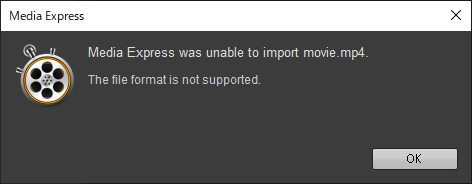
Media Expressに動画をインポートすると次のようなエラーが表示された
Media Express was unable to import movie.mp4.
The file format is not supported.
サポートしていないファイルフォーマットだと表示されているが、複数の形式のファイルを読み込ませても同じエラーが出た。
原因と対処法
読み込もうとした動画ファイルのパスに日本語が含まれていたことが原因だった。 フォルダ名を修正すると読み込めるようになった。
【gstreamer+python】画像から動画を作成する
画像から圧縮された動画を作成する方法を調べた
パイプラインは以下

| プラグイン名 | 概要 | input(sink) | output(src) | 詳細 |
|---|---|---|---|---|
| fdsrc | ファイルディスクリプタからデータを読み取るソースエレメント。標準入力/パイプ/ソケットなどからのデータストリームを受け取る | - | any | link |
| videoparse | バイトストリームをビデオフレームに変換する | any | video/x-raw | link |
| videoconvert | さまざまなビデオ形式間でビデオフレームを変換する | video/x-raw | video/x-raw | link |
| x264enc | 生のデータをH264圧縮データにエンコードする | video/x-raw | video/x-h264 | link |
| mp4mux | オーディオとビデオをMP4ファイルに多重化する | video/x-h264 or video/x-h265 *1 | video/quicktime | link |
| filesink | 受け取ったデータをファイルに書き出す | any | - | link |
pythonで書くとこうなる
import numpy as np
import subprocess

# パラメータ設定
width, height = 1280, 720  # 画像サイズ
num_frames = 100  # フレーム数
fps = 30  # フレームレート
output_video = "output.mp4"

# GStreamer コマンド (パイプ経由でデータを送信)
gst_cmd = (
    "gst-launch-1.0 "
    + "fdsrc "
    + f"! videoparse format=gray8 width={width} height={height} framerate={fps}/1 "
    + "! videoconvert "
    + "! x264enc "
    + "! mp4mux "
    + f"! filesink location={output_video}"
)

# subprocess で GStreamer を実行 (パイプを通してデータを送る)
process = subprocess.Popen(gst_cmd, shell=True, stdin=subprocess.PIPE)

try:
    for _ in range(num_frames):
        # ランダムなノイズ画像 (グレースケール)
        noise = np.random.randint(0, 256, (height, width), dtype=np.uint8)

        # GStreamer にデータを送信
        process.stdin.write(noise.tobytes())

    print(f"Recording completed. Video saved as {output_video}")

except Exception as e:
    print("Error:", e)

finally:
    # GStreamer のパイプラインを終了
    process.stdin.close()
    process.wait()
*1:音声のsinkもあるが、動画のみ記載
gstreamerに入門してみる
gstreamerを使う機会があったのでせっかくなら仲良くなりたいと思いました
最近のお気に入りの勉強法は、とりあえずChatGPT先生にプログラムのテーマを簡単なものから列挙してもらう方法。
GStreamer の習熟度別 20 段階リスト
| 段階 | スキルレベル | 説明 |
|---|---|---|
| 1 | 基礎 | GStreamer のインストールと基本コマンド (gst-launch-1.0) の実行 |
| 2 | 基礎 | gst-inspect-1.0 で利用可能なプラグインやエレメントの情報を取得 |
| 3 | 基礎 | シンプルなオーディオ/ビデオパイプラインの作成 (audiotestsrc / videotestsrc) |
| 4 | 基礎 | gst-launch-1.0 でファイルの再生 (filesrc + decodebin + autovideosink) |
| 5 | 基礎 | gst-launch-1.0 でWebカメラの映像を表示 (v4l2src + autovideosink) |
| 6 | 初級 | C 言語での GStreamer アプリケーション開発 (gst_parse_launch) |
| 7 | 初級 | gst_element_set_state() でパイプラインの制御 (PLAYING, PAUSED, NULL) |
| 8 | 初級 | gst_bus_timed_pop_filtered() を使ってエラーハンドリング |
| 9 | 初級 | gst_pad を使用してエレメント間の接続状態を確認 |
| 10 | 中級 | gst_caps を利用してエレメントのフォーマットを指定 |
| 11 | 中級 | gst_buffer を取得して映像や音声データを直接処理 |
| 12 | 中級 | gst_appsrc / gst_appsink を用いたカスタムデータの送受信 |
| 13 | 中級 | gst-launch-1.0 でストリーミング配信 (rtmpsink / udpsink) |
| 14 | 中級 | gst-python を使って GStreamer を Python で制御 |
| 15 | 上級 | gstreamer-rtsp-server を使った RTSP サーバーの構築 |
| 16 | 上級 | gst_parse_launch() を使わず、手動でエレメントを作成・接続 |
| 17 | 上級 | gst_dynamic_pipeline を利用した動的なパイプラインの変更 |
| 18 | 上級 | gst_plugin_register() を使って独自の GStreamer プラグインを作成 |
| 19 | 上級 | GstBufferPool を使用した効率的なメモリ管理 |
| 20 | 最上級 | GStreamer のソースコードを解析し、コアライブラリの拡張や最適化 |
かいつまんで実行していく
基礎 | gst-inspect-1.0 で利用可能なプラグインやエレメントの情報を取得
audiotestsrcプラグインの情報を表示するには以下のコマンドを実行する
gst-inspect-1.0 audiotestsrc
基礎 | シンプルなオーディオ/ビデオパイプラインの作成 (audiotestsrc / videotestsrc) |
テスト音声を再生
gst-launch-1.0 audiotestsrc ! audioconvert ! autoaudiosink
-> 聴力検査みたいな音が鳴る
テスト映像を再生
gst-launch-1.0 videotestsrc ! videoconvert ! autovideosink
-> カラーバーが表示される
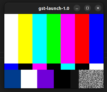
プラグインを!で接続する感じですね
基礎 | gst-launch-1.0 でファイルの再生 (filesrc + decodebin + autovideosink)
gst-launch-1.0 filesrc location=./dog.webm ! decodebin ! videoconvert ! autovideosink
| plugin | 概要 |
|---|---|
| filesrc | ローカルファイルシステム内のファイルからデータを読み取る |
| decodebin | 入力されたメディアファイルのフォーマット(コーデック)を自動で判別し、適切なデーコーダーを選択してデコードする |
| videoconvert | デコードされた映像データのピクセルフォーマットを皇族のエレメントが受け取れる形式に変換する |
| autovideosink | システム環境に応じた適切な映像出力を自動選択して再生する |
基礎 | gst-launch-1.0 でWebカメラの映像を表示 (v4l2src + autovideosink)
ls /dev/video*

# /dev/video0  /dev/video1
video0を指定して下記コマンドを実行すると映像が出力される
gst-launch-1.0 v4l2src device="/dev/video0" ! video/x-raw,format=YUY2 ! videoconvert ! autovideosink

バックアップ線図の起源を調べた
強化学習のことを調べているとバックアップ線図がよく出てくるけど、バックアップ線図自体の説明がないし、いまいち起源も微妙なので調べた
そもそもバックアップとは
価値ベースの強化学習ではアクションを決定するために価値関数を使用する。価値関数には状態価値関数と行動価値関数があるが、ここでは状態価値関数について述べる。
状態価値関数は状態の関数であり、入力された状態に対応する価値を返す。ここで価値とは状態
から得られる累積報酬
の期待値である。累積報酬
は次のように定義される。
この期待値を用いると、状態価値関数は以下のように表される。
この価値関数は最初は任意の初期値が設定され、学習によって最適な値に近づいていく。
状態での価値関数を更新するには次のような更新式を用いる
は学習率であり、更新の大きさを制御する。
例えばTD法であれば次のようになる
ここでは即時報酬、
は割引率で、未来の報酬の重要度を調整する。
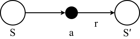
このように
を
や即時報酬
を使って更新することをバックアップと言う。バックアップは、状態間で価値が伝播されるプロセスを指す。
【本題】バックアップ線図の起源
ChatGPTに聞いた
Q, マルコフ決定過程を表現するために使用されるバックアップ線図をデザインしたのは誰ですか
マルコフ決定過程(MDP)を表現するために用いられるバックアップダイアグラムは、MDPにおける状態、行動、報酬、遷移の関係を示すグラフィカルなツールである。バックアップ・ダイアグラムの正確な起源は1人の人物によるものではないが、この概念は動的計画法と強化学習における基礎的な研究と密接に関連している:
Richard Bellman:1950年代に動的計画法を導入したことで知られるBellmanは、ベルマン方程式を定式化した。
Andrew BartoとRichard Sutton: これらの研究者は、彼らの代表的な著書『Reinforcement Learning: An Introduction』において、バックアップ・ダイアグラムの使用を普及させた。この本では、動的計画法、モンテカルロ法、時間差学習などの手法において、値関数がどのように更新されるかを可視化するために、バックアップ・ダイアグラムを多用して強化学習の概念を体系的に説明している。
バックアップ・ダイアグラムは、特に強化学習において、MDPを教え、理解するための標準的な可視化ツールである。バックアップ・ダイアグラムが広く採用されるようになったのは、これらのプロセスを形式化し、図解化したSuttonとBartoの研究に負うところが大きい。
ほんまかいな
「sutton backup diagaram」でググったらブリティッシュコロンビア大学の授業の資料がヒットした
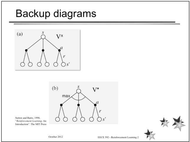
この資料ではバックアップ線図を次のように説明している
バックアップ・ダイアグラム
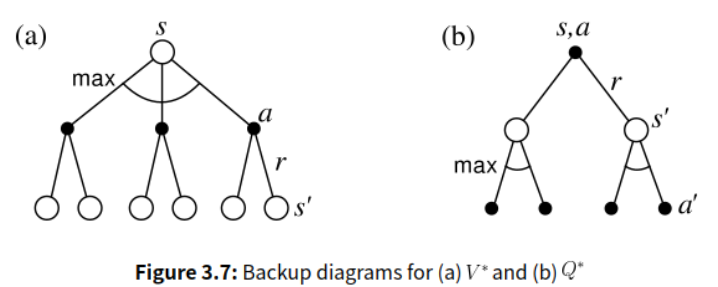
サットンとバルトーはバックアップ・ダイアグラムという概念を紹介している。これらはRLを理解する上で役に立つが、まずはその表記法を理解する必要がある。例を以下の図に示す。(a)は
のバックアップ図を示し、(b)は最適な(貪欲な)方針のみに適用される。(a)では、ルートノードの更新、つまりバックアップは、すべての後継ノードの関数であり、いわゆるフルバックアップである。(b)では、バックアップは将来のノードのサンプルである。円弧は、選択をしなければならないポイントを示している。最適ポリシーの場合,これは貪欲な選択である.上の図も下の図も動的計画法に適用でき,TD学習には適用できない.
この資料は図つきである。しかも『Reinforcement Learning: An Introduction』からの引用との記述もある。 『Reinforcement Learning: An Introduction』は、1st editionならネットで見れる
3.7章 Value Functionsで初めてバックアップ線図がでてきた
この図がバックアップ線図と呼ばれる理由も書かれている
このような図をバックアップ線図と呼ぶのは、強化学習法の核心である更新操作やバックアップ操作の基礎となる関係を図式化したものだからである。これらの操作は、状態(または状態とアクションのペア)の値情報を、その後継の状態(または状態とアクションのペア)から状態(または状態とアクションのペア)に戻します。本書では、説明するアルゴリズムをグラフィカルに要約するために、バックアップ線図を使用する。(遷移グラフとは異なり、バックアップ線図の状態ノードは必ずしも異なる状態を表すわけではないことに注意。また、バックアップ線図では時間は常に下向きに流れるので、明示的な矢印は省略する)。
なるほど、いかにもこれまではメジャーではなかったのが分かる説明である
バックアップ操作といっているのが何なのか気になるが、一旦おいておいて、他にも記述があるか探す
次のページ、3.8章 Optimal Value Functionsでは、最適方策が得られている状態のバックアップ線図の記法がわかる
まとめ
Reinforcement Learning: An Introductionの中で使用されているのがおそらく最初。 バックアップ操作を視覚的に表現するために採用されている。
Isaac Gymでアセットを読み込んで動かすまで
インストールするとサンプルのプログラムが複数用意されていますが、思ったより内容がリッチで、全体像をざっくり把握するのが難しかったです。
そこで、サンプルプログラムの内容をより簡易にしたプログラムを作成し、理解に努めました。
成果物
~/isaacgym/python/examplesの中にfranka_attractor.pyというファイルがあります。
これを実行するとシミュレータ内に数十体のfrankaロボットが読み込まれ、アームを周期的に動作させます。
このプログラムをベースにして、ロボットを1体だけ呼び出し、同じ動作をさせるプログラムを作成しました。
# my_franka.py

import math
from isaacgym import gymapi
from isaacgym import gymutil

# Initialize gym
gym = gymapi.acquire_gym()

# Parse arguments
args = gymutil.parse_arguments(description="Franka load program")

# configure sim
sim_params = gymapi.SimParams()
sim_params.dt = 1.0 / 60.0
sim_params.substeps = 2
if args.physics_engine == gymapi.SIM_FLEX:
    sim_params.flex.solver_type = 5
    sim_params.flex.num_outer_iterations = 4
    sim_params.flex.num_inner_iterations = 15
    sim_params.flex.relaxation = 0.75
    sim_params.flex.warm_start = 0.8
elif args.physics_engine == gymapi.SIM_PHYSX:
    sim_params.physx.solver_type = 1
    sim_params.physx.num_position_iterations = 4
    sim_params.physx.num_velocity_iterations = 1
    sim_params.physx.num_threads = args.num_threads
    sim_params.physx.use_gpu = args.use_gpu

sim_params.use_gpu_pipeline = False
if args.use_gpu_pipeline:
    print("WARNING: Forcing CPU pipeline.")

sim = gym.create_sim(
    args.compute_device_id, args.graphics_device_id, args.physics_engine, sim_params
)

if sim is None:
    print("*** Failed to create sim")
    quit()

# Create viewer
viewer = gym.create_viewer(sim, gymapi.CameraProperties())
if viewer is None:
    print("*** Failed to create viewer")
    quit()

# Add ground plane
plane_params = gymapi.PlaneParams()
gym.add_ground(sim, plane_params)

# Load franka asset
asset_root = "../../assets"
franka_asset_file = "urdf/franka_description/robots/franka_panda.urdf"

asset_options = gymapi.AssetOptions()
asset_options.fix_base_link = True
asset_options.flip_visual_attachments = True
asset_options.armature = 0.01

print("Loading asset '%s' from '%s'" % (franka_asset_file, asset_root))
franka_asset = gym.load_asset(sim, asset_root, franka_asset_file, asset_options)

"""
アセットはロードしただけではシミュレータ内に読み込まれない。
アセットをシミュレータ内に配置するためには、アセットをインスタンス化する必要がある。
"""
# Set up the env grid
spacing = 1.0
env_lower = gymapi.Vec3(-spacing, 0.0, -spacing)
env_upper = gymapi.Vec3(spacing, spacing, spacing)

# Attractor setup
attractor_handles = []
attractor_properties = gymapi.AttractorProperties()
attractor_properties.stiffness = 5e5
attractor_properties.damping = 5e3

# Make attractor in all axes
attractor_properties.axes = gymapi.AXIS_ALL
pose = gymapi.Transform()
pose.p = gymapi.Vec3(0, 0.0, 0.0)
pose.r = gymapi.Quat(-0.707107, 0.0, 0.0, 0.707107)

# Create helper geometry used for visualization
# Create an wireframe axis
axes_geom = gymutil.AxesGeometry(0.1)
# Create an wireframe sphere
sphere_rot = gymapi.Quat.from_euler_zyx(0.5 * math.pi, 0, 0)
sphere_pose = gymapi.Transform(r=sphere_rot)
sphere_geom = gymutil.WireframeSphereGeometry(
    0.03, 12, 12, sphere_pose, color=(1, 0, 0)
)


# sim : sim インスタンス
# env_lower : gymapi.Vec3 環境空間の下限
# env_upper : gymapi.Vec3 環境空間の上限
# num_envs : int 環境の数
env = gym.create_env(sim, env_lower, env_upper, 1)

# env: 環境のハンドル
# asset: アセットのハンドル
# pose: アセットが最初に配置される位置と姿勢
# name: アクターの名前
# group: アクターが所属する衝突グループ
# filter: 衝突をマスクするためのフィルタ
franka_handle = gym.create_actor(env, franka_asset, pose, "franka", 0, 2)

print("Created franka with handle", franka_handle)
franka_hand = "panda_hand"
body_dict = gym.get_actor_rigid_body_dict(env, franka_handle)
props = gym.get_actor_rigid_body_states(env, franka_handle, gymapi.STATE_POS)
hand_handle = body = gym.find_actor_rigid_body_handle(env, franka_handle, franka_hand)

# Initialize the attractor
attractor_properties.target = props["pose"][:][body_dict[franka_hand]]
attractor_properties.target.p.y -= 0.1
attractor_properties.target.p.z = 0.1
attractor_properties.rigid_handle = hand_handle

# Draw axes and sphere at attractor location
gymutil.draw_lines(axes_geom, gym, viewer, env, attractor_properties.target)
gymutil.draw_lines(sphere_geom, gym, viewer, env, attractor_properties.target)

# 定義されたプロパティを使用して、選択した環境のアトラクターを作成する
attractor_handle = gym.create_rigid_body_attractor(env, attractor_properties)

# get joint limits and ranges for Franka
franka_dof_props = gym.get_actor_dof_properties(env, franka_handle)
franka_lower_limits = franka_dof_props["lower"]
franka_upper_limits = franka_dof_props["upper"]
franka_ranges = franka_upper_limits - franka_lower_limits
franka_mids = 0.5 * (franka_upper_limits + franka_lower_limits)
franka_num_dofs = len(franka_dof_props)

# override default stiffness and damping values
franka_dof_props["stiffness"].fill(1000.0)
franka_dof_props["damping"].fill(1000.0)

# Give a desired pose for first 2 robot joints to improve stability
franka_dof_props["driveMode"][0:2] = gymapi.DOF_MODE_POS

franka_dof_props["driveMode"][7:] = gymapi.DOF_MODE_POS
franka_dof_props["stiffness"][7:] = 1e10
franka_dof_props["damping"][7:] = 1.0

gym.set_actor_dof_properties(env, franka_handle, franka_dof_props)


def update_franka(t):
    gym.clear_lines(viewer)

    # Update attractor target from current franka state
    attractor_properties = gym.get_attractor_properties(env, attractor_handle)
    pose = attractor_properties.target
    pose.p.x = 0.2 * math.sin(1.5 * t)
    pose.p.y = 0.7 + 0.1 * math.cos(2.5 * t)
    pose.p.z = 0.2 * math.cos(1.5 * t)

    gym.set_attractor_target(env, attractor_handle, pose)

    # Draw axes and sphere at attractor location
    gymutil.draw_lines(axes_geom, gym, viewer, env, pose)
    gymutil.draw_lines(sphere_geom, gym, viewer, env, pose)


# Set updated stiffness and damping properties
gym.set_actor_dof_properties(env, franka_handle, franka_dof_props)

# Set ranka pose so that each joint is in the middle of its actuation range
franka_dof_states = gym.get_actor_dof_states(env, franka_handle, gymapi.STATE_NONE)
for j in range(franka_num_dofs):
    franka_dof_states["pos"][j] = franka_mids[j]
gym.set_actor_dof_states(env, franka_handle, franka_dof_states, gymapi.STATE_POS)

# Point camera at environments
cam_pos = gymapi.Vec3(-4.0, 4.0, -1.0)
cam_target = gymapi.Vec3(0.0, 2.0, 1.0)
gym.viewer_camera_look_at(viewer, None, cam_pos, cam_target)

# Time to wait in seconds before moving robot
next_franka_update_time = 1.5

while not gym.query_viewer_has_closed(viewer):
    # Every 0.01 seconds the pose of the attactor is updated
    t = gym.get_sim_time(sim)
    if t >= next_franka_update_time:
        update_franka(t)
        next_franka_update_time += 0.01

    # Step the physics
    gym.simulate(sim)
    gym.fetch_results(sim, True)

    # Step rendering
    gym.step_graphics(sim)
    gym.draw_viewer(viewer, sim, False)
    gym.sync_frame_time(sim)

print("Done")

gym.destroy_viewer(viewer)
gym.destroy_sim(sim)
処理を箇条書きすると以下の通りになります。
- 初期化
- 動作
- simの経過時間をチェックし、ロボットの制御周期を超えていればロボットの姿勢を更新する
クラス図
classDiagram
    class Gym
    class SimParams
    class FlexParams
    class PhysXParams
    class Sim
    class Viewer
    class Env{
        +env_lower : Vec3
        +env_upper : Vec3
    }
    class Actor
    class Asset

    class CameraProperties
    class PlaneParams{
        +distance
        +dynamic_friction
        +static_friction
        +restitution
        segmentation_id
    }
    class AssetOptions {
        +fix_base_link : bool
        +flip_visual_attachments : bool
        +armature : float
    }
    class DOFProperties {
        +lower : List[float]
        +upper : List[float]
        +stiffness : List[float]
        +damping : List[float]
        +driveMode : List[int]
    }

    class DOFStates {
        +pos : List[float]
    }

    class AttractorProperties {
        +target : Transform
        +stiffness : float
        +damping : float
        +axes : int
        +rigid_handle : int
    }
    class Attractor

    Gym -- Sim
    Gym --"*" Env
    Gym -- Viewer

    SimParams --> FlexParams
    SimParams --> PhysXParams
        Sim o-- SimParams
        Sim o-- PlaneParams
        Sim o-- Asset
        Sim -- Env : 管理する
        Env o-- Actor
        Env o-- Attractor
        Asset o-- AssetOptions
        Viewer o-- CameraProperties
        Attractor o-- AttractorProperties
        Actor o-- DOFStates
        Actor o-- DOFProperties
TreeViewをWinUI3/C++で実装する方法
はじめに
WinUI3でTreeViewを使用したコントロールを実装する方法を解説します。 公式ドキュメントにはC#の解説はあるものの、C++の解説がなかったので苦労しました。 動作するサンプルはGitHubに公開しています。 -> TreeViewExample
つくるもの
このようなツリー状の要素を作成します

ポイント
モデルに自身の名前と子要素を持たせる
ツリーの各要素としてTreeItemViewModelクラスを作成します。
このクラスはツリーに表示される自身の名前と自身の子要素となるVectorをメンバに持ちます。
そしてそれぞれの要素をXAMLの要素にバインドします。 バインドについては階層データ ソースへのバインドを参考にしました。
namespace winrt::TreeViewExample::implementation
{
    struct TreeItemViewModel : TreeItemViewModelT<TreeItemViewModel>
    {
    public:
        TreeItemViewModel();
        TreeItemViewModel(hstring);

        hstring Name();
        Windows::Foundation::Collections::IObservableVector<TreeViewExample::TreeItemViewModel> Children();

    private:
        hstring name_;
        Windows::Foundation::Collections::IObservableVector<TreeViewExample::TreeItemViewModel> children_{nullptr};
    };
}
winrt::single_threaded_observable_vectorを使用する
子要素のリストを持つ型にはwinrt::single_threaded_observable_vectorを使用します。
(この情報が本当にどこにも書いてなかった)
ListViewに関する記事ですが、下記の記事を参考にしました C++/WinRTでUWPその5 データバインディングその3 List~コントロールへのバインド
TreeItemViewModel::TreeItemViewModel() : name_(L"default")
{
    children_ = winrt::single_threaded_observable_vector<TreeViewExample::TreeItemViewModel>();
}
implementationを区別する
子要素を親のリストにappendする際にインスタンス化しますが、その際にwinrt::makeを使用します。
で、右辺ではプロジェクト名::implementation::クラス名ですが、左辺はプロジェクト名::クラス名となっています。
自分はこのあたりの区別をあいまいにやっていたのではまりました。
TreeViewExample::TreeItemViewModel parent1 = winrt::make<TreeViewExample::implementation::TreeItemViewModel>(L"Parent1");
各ファイルの解説
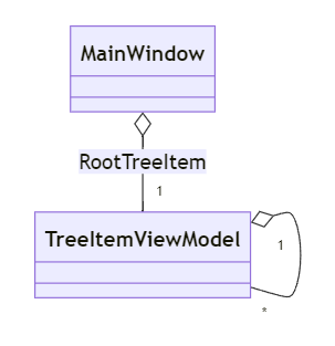
今回は最小の要素で実装しているのでクラスは2つです。
TreeItemViewModel.idl
namespace TreeViewExample
{
    [bindable]
    [default_interface]
    runtimeclass TreeItemViewModel
    {
        TreeItemViewModel();

        String Name{ get; };
        Windows.Foundation.Collections.IObservableVector<TreeItemViewModel> Children{ get; };
    }
}
TreeItemViewModel.h
namespace winrt::TreeViewExample::implementation
{
    struct TreeItemViewModel : TreeItemViewModelT<TreeItemViewModel>
    {
    public:
        TreeItemViewModel();
        TreeItemViewModel(hstring);

        hstring Name();
        Windows::Foundation::Collections::IObservableVector<TreeViewExample::TreeItemViewModel> Children();

    private:
        hstring name_;
        Windows::Foundation::Collections::IObservableVector<TreeViewExample::TreeItemViewModel> children_{nullptr};
    };
}
前述した通り、自身の名前と子要素のリストを持ちます。
Windows::Foundation::Collections::IObservableVector型を使用します。
ドキュメントを読むとC#ではObservableCollection<T>を使用するって書いてあるので、C++にも同様のクラスがあるのかと思ったら別なんですね。
TreeItemViewModel.cpp
namespace winrt::TreeViewExample::implementation
{
    TreeItemViewModel::TreeItemViewModel() : name_(L"default")
    {
        children_ = winrt::single_threaded_observable_vector<TreeViewExample::TreeItemViewModel>();
    }

    TreeItemViewModel::TreeItemViewModel(hstring name) : name_(name)
    {
        children_ = winrt::single_threaded_observable_vector<TreeViewExample::TreeItemViewModel>();
    }

    hstring TreeItemViewModel::Name()
    {
        return name_;
    }

    Windows::Foundation::Collections::IObservableVector<TreeViewExample::TreeItemViewModel> TreeItemViewModel::Children()
    {
        return children_;
    }
}
MainWindow.idl
import "TreeItemViewModel.idl";

namespace TreeViewExample
{
    [default_interface]
    runtimeclass MainWindow : Microsoft.UI.Xaml.Window
    {
        MainWindow();
        TreeItemViewModel RootTreeItem{ get; };
    }
}
MainWindowを編集していきます。 Xaml要素からルートとなるTreeItemViewModel にアクセスするのでゲッターにアクセスできるようにしています。
MainWindow.h
namespace winrt::TreeViewExample::implementation
{
    struct MainWindow : MainWindowT<MainWindow>
    {
    public:
        MainWindow();
        TreeViewExample::TreeItemViewModel RootTreeItem();

    private:
        TreeViewExample::TreeItemViewModel tree_item_view_model_{ nullptr };
    };
}
MainWindow.cpp
using namespace winrt;
using namespace Microsoft::UI::Xaml;

namespace winrt::TreeViewExample::implementation
{
    MainWindow::MainWindow()
    {
        tree_item_view_model_ = winrt::make<TreeViewExample::implementation::TreeItemViewModel>(L"Root");

        TreeViewExample::TreeItemViewModel parent1 = winrt::make<TreeViewExample::implementation::TreeItemViewModel>(L"Parent1");
        TreeViewExample::TreeItemViewModel parent2 = winrt::make<TreeViewExample::implementation::TreeItemViewModel>(L"Parent2");
        TreeViewExample::TreeItemViewModel child11 = winrt::make<TreeViewExample::implementation::TreeItemViewModel>(L"Child11");
        TreeViewExample::TreeItemViewModel child12 = winrt::make<TreeViewExample::implementation::TreeItemViewModel>(L"Child12");
        TreeViewExample::TreeItemViewModel child21 = winrt::make<TreeViewExample::implementation::TreeItemViewModel>(L"Child21");
        TreeViewExample::TreeItemViewModel child22 = winrt::make<TreeViewExample::implementation::TreeItemViewModel>(L"Child22");

        parent1.Children().Append(child11);
        parent1.Children().Append(child12);
        parent2.Children().Append(child21);
        parent2.Children().Append(child22);

        tree_item_view_model_.Children().Append(parent1);
        tree_item_view_model_.Children().Append(parent2);

        InitializeComponent();
    }

    TreeViewExample::TreeItemViewModel MainWindow::RootTreeItem()
    {
        return tree_item_view_model_;
    }
}
MainWindowのコンストラクタで親子関係の設定をしています。 ツリー要素の名前はTreeItemViewModelのコンストラクタで、子要素はChildrenにappendしています。
MainWindow.xaml
<?xml version="1.0" encoding="utf-8"?>
<Window
    x:Class="TreeViewExample.MainWindow"
    xmlns="http://schemas.microsoft.com/winfx/2006/xaml/presentation"
    xmlns:x="http://schemas.microsoft.com/winfx/2006/xaml"
    xmlns:local="using:TreeViewExample"
    xmlns:d="http://schemas.microsoft.com/expression/blend/2008"
    xmlns:mc="http://schemas.openxmlformats.org/markup-compatibility/2006"
    mc:Ignorable="d">

    <StackPanel Orientation="Horizontal" HorizontalAlignment="Center" VerticalAlignment="Center">
        <TreeView x:Name="myTreeView" Width="200" Height="200" ItemsSource="{x:Bind RootTreeItem.Children}">
            <TreeView.ItemTemplate>
                <DataTemplate x:DataType="local:TreeItemViewModel">
                    <TreeViewItem x:Name="TreeItem" ItemsSource="{x:Bind Children}" Content="{x:Bind Name}"/>
                </DataTemplate>
            </TreeView.ItemTemplate>
        </TreeView>
    </StackPanel>
</Window>
ItemsSourceに子要素を、Contentに名前をバインドしています。
参考リンク
【ROS】RViz上でロボットの手先の軌跡をマーカー表示する
RViz上でロボットの手先の軌跡をマーカー表示する方法を記します。
使用環境はROS1 noeticです。
subscriverノードを起動する
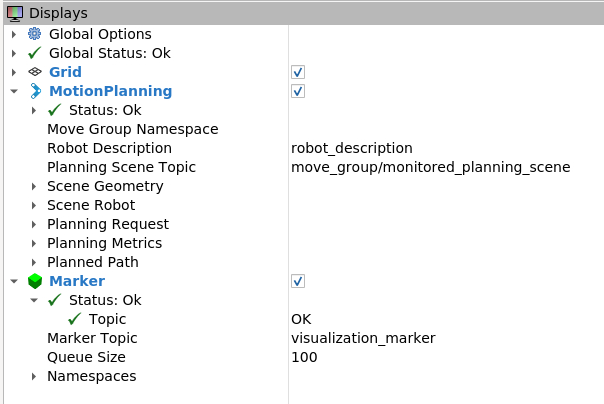
RVizを起動し、DisplaysにMarkerを追加します。 ここにtopic名が表示されるので、ここに向けてマーカーの情報をpubします。
publisherノードを起動する
マーカー情報をpubするノードを起動します。 サンプルコードを以下に示します。
#! /usr/bin/env python3

import rospy
from visualization_msgs.msg import Marker
from std_msgs.msg import Header, ColorRGBA
from geometry_msgs.msg import Pose, Point, Vector3, Quaternion

FLAME_ID = "prbt_tcp"

class TrajectoryInteractiveMarkers:
    def __init__(self):
        self.count = 0
        self.marker_publisher = rospy.Publisher('visualization_marker', Marker, queue_size=5)
        # タイマーを設定し、0.5秒ごとにpublish_markerメソッドを呼び出す
        rospy.Timer(rospy.Duration(0.5), self.publish_marker)

    def publish_marker(self, event):
        self.marker = Marker(
                    type=Marker.SPHERE,
                    id=self.count,
                    lifetime=rospy.Duration(10),  # マーカーの持続時間を10秒に設定
                    pose=Pose(Point(0,0,0.01), Quaternion(0, 0, 0, 1)),
                    scale=Vector3(0.03, 0.03, 0.03),
                    header=Header(frame_id=FLAME_ID),
                    color=ColorRGBA(0.0, 1.0, 0.0, 0.8)  # 緑色の半透明マーカー
                    )
        self.marker_publisher.publish(self.marker)
        rospy.loginfo('Marker published')
        self.count += 1

if __name__ == '__main__':
    rospy.init_node("trajectory_interactive_markers_node", anonymous=True)
    trajectory_interactive_markers = TrajectoryInteractiveMarkers()
    rospy.spin()  # rospy.spin()を使用してイベントループを開始
Markerのメッセージに必要な情報を詰め込んでいます。
type
マーカーの形状を指定します。
id
重複しないIDを指定します。
lifetime
マーカーの生存時間を指定します。 ここでは10秒としています。
pose
マーカーの位置と姿勢です。 今回はロボット本体と重なって表示されることを避けるためにZ方向に0.01だけオフセットしています。
scale
サイズの指定です。
header(frame_id)
マーカーを表示する座標系を指定します。 使用するロボットに合わせて変更する必要があります。
coloer
マーカーの色と透明度です。
動作の様子
参考
Visualising the real time trajectory path using markers - ROS Answers: Open Source Q&A Forum
[ROS Q&A] 094 - Visualising the real time trajectory path using markers - YouTube
